Truss bridge
 Truss bridge for a single track railway, converted to pedestrian use and pipeline support | |
| Ancestor | Beam bridge[citation needed] |
|---|---|
| Related | None |
| Descendant | Cantilever bridge, truss arch bridge, transporter bridge, lattice bridge[citation needed] |
| Carries | Pedestrians, pipelines, automobiles, trucks, light rail, heavy rail |
| Span range | Short to medium – not very long unless it is continuous |
| Material | Timber, iron, steel, reinforced concrete, prestressed concrete |
| Movable | May be movable – see movable bridge |
| Design effort | Medium |
Falsework required | Depends upon length, materials, and degree of prefabrication |
A truss bridge is a bridge whose load-bearing superstructure is composed of a truss, a structure of connected elements usually forming triangular units. The connected elements (typically straight) may be stressed from tension, compression, or sometimes both in response to dynamic loads. Truss bridges are one of the oldest types of modern bridges. The basic types of truss bridges shown in this article have simple designs which could be easily analyzed by 19th and early 20th-century engineers. A truss bridge is economical to construct because it uses materials efficiently.
Contents
1 Design
1.1 Model bridges
2 History in the United States
3 Roadbed types
4 Truss types used in bridges
4.1 Allan truss
4.2 Bailey bridge
4.3 Baltimore truss
4.4 Bollman truss
4.5 Bowstring arch truss
4.6 Brown truss
4.7 Brunel truss
4.8 Burr arch truss
4.9 Cantilevered truss
4.10 Fink truss
4.11 Howe truss
4.12 K truss
4.13 Kingpost truss
4.14 Lattice truss (Town's lattice truss)
4.15 Lenticular truss
4.16 Long truss
4.17 Parker (camelback) truss
4.18 Pegram truss
4.19 Pennsylvania (Petit) truss
4.20 Post truss
4.21 Pratt truss
4.22 Queenpost truss
4.23 Smith truss
4.24 Thatcher truss
4.25 Truss arch
4.26 Vierendeel truss
4.27 Waddell truss
4.28 Warren truss
4.29 Whipple truss
5 Truss bridge video
6 References
7 Footnotes
8 External links
Design

The integral members of a truss bridge[1]
The nature of a truss allows the analysis of its structure using a few assumptions and the application of Newton's laws of motion according to the branch of physics known as statics. For purposes of analysis, trusses are assumed to be pin jointed where the straight components meet. This assumption means that members of the truss (chords, verticals and diagonals) will act only in tension or compression. A more complex analysis is required where rigid joints impose significant bending loads upon the elements, as in a Vierendeel truss.
In the bridge illustrated in the infobox at the top, vertical members are in tension, lower horizontal members in tension, shear, and bending, outer diagonal and top members are in compression, while the inner diagonals are in tension. The central vertical member stabilizes the upper compression member, preventing it from buckling. If the top member is sufficiently stiff then this vertical element may be eliminated. If the lower chord (a horizontal member of a truss) is sufficiently resistant to bending and shear, the outer vertical elements may be eliminated, but with additional strength added to other members in compensation. The ability to distribute the forces in various ways has led to a large variety of truss bridge types. Some types may be more advantageous when wood is employed for compression elements while other types may be easier to erect in particular site conditions, or when the balance between labor, machinery and material costs have certain favorable proportions.
The inclusion of the elements shown is largely an engineering decision based upon economics, being a balance between the costs of raw materials, off-site fabrication, component transportation, on-site erection, the availability of machinery and the cost of labor. In other cases the appearance of the structure may take on greater importance and so influence the design decisions beyond mere matters of economics. Modern materials such as prestressed concrete and fabrication methods, such as automated welding, and the changing price of steel relative to that of labor have significantly influenced the design of modern bridges.
Model bridges
A pure truss can be represented as a pin-jointed structure, one where the only forces on the truss members are tension or compression, not bending. This is used in the teaching of statics, by the building of model bridges from spaghetti. Spaghetti is brittle and although it can carry a modest tension force, it breaks easily if bent. A model spaghetti bridge thus demonstrates the use of a truss structure to produce a usefully strong complete structure from individually weak elements.
History in the United States

Warren-type through-truss of the former Seaboard Air Line Railway, located near the village of Willow, Florida; abandoned since the mid-1980s
Because wood was in abundance, early truss bridges would typically use carefully fitted timbers for members taking compression and iron rods for tension members, usually constructed as a covered bridge to protect the structure. In 1820 a simple form of truss, Town's lattice truss, was patented, and had the advantage of requiring neither high labor skills nor much metal. Few iron truss bridges were built in the United States before 1850.
Truss bridges became a common type of bridge built from the 1870s through the 1930s. Examples of these bridges still remain across the US, but their numbers are dropping rapidly, as they are demolished and replaced with new structures. As metal slowly started to replace timber, wrought iron bridges in the US started being built on a large scale in the 1870s. Bowstring truss bridges were a common truss design during this time, with their arched top chords. Companies like the Massillon Bridge Company of Massillon, Ohio and the King Bridge Company of Cleveland, Ohio became well-known, as they marketed their designs to cities and townships. The bowstring truss design (photo) fell out of favor due to a lack of durability, and gave way to the Pratt truss design, which was stronger. Again, the bridge companies marketed their designs, with the Wrought Iron Bridge Company in the lead. As the 1880s and 1890s progressed, steel began to replace wrought iron as the preferred material. Other truss designs were used during this time, including the camel-back. By the 1910s, many states developed standard plan truss bridges, including steel Warren pony truss bridges. As the 1920s and 1930s progressed, some states, such as Pennsylvania, continued to build steel truss bridges, including massive steel through-truss bridges for long spans. Other states, such as Michigan, used standard plan concrete girder and beam bridges, and only a limited number of truss bridges were built.
Roadbed types
The truss may carry its roadbed on top, in the middle, or at the bottom of the truss. Bridges with the roadbed at the top or the bottom are the most common as this allows both the top and bottom to be stiffened, forming a box truss. When the roadbed is atop the truss it is called a deck truss (an example of this was the I-35W Mississippi River bridge). When the truss members are both above and below the roadbed it is called a through truss (an example of this application is the Pulaski Skyway), and where the sides extend above the roadbed but are not connected, a pony truss or half-through truss.
Sometimes both the upper and lower chords support roadbeds, forming a double-decked truss. This can be used to separate rail from road traffic or to separate the two directions of automobile traffic and so avoiding the likelihood of head-on collisions.
Since through truss bridges have supports located over the bridge deck, they are susceptible to being hit by overheight loads when used on highways – the I-5 Skagit River Bridge collapsed after such a strike, and such impacts were common and required frequent repairs before the collapse.[2]

Deck truss railroad bridge over the Erie Canal in Lockport, New York

The four span through truss General Hertzog Bridge over the Orange River at Aliwal North carries vehicular traffic

The through truss Skagit River Bridge on Interstate 5 collapsed after an overhead support was hit by a passing truck

Pony truss bridge of reinforced concrete

Sky Gate Bridge R at Kansai International Airport, Osaka, Japan, is the longest double-decked truss bridge in the world. It carries three lanes of automobile traffic on top and two of rail below over nine truss spans.
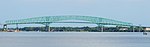
The Hart Bridge is a continuous, cantilevered truss bridge with an unusual design that combines a suspended road deck on the 332-metre (1,088 ft) main span and through truss decks on the adjacent approach spans.
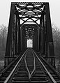
A railway bridge with a rail track in Leflore County, Mississippi
Side view of the iron truss railway bridge over Mura River in Mursko Središće, Croatia


Truss types used in bridges
Bridges are the most widely known examples of truss use. There are many types, many dating back hundreds of years. Below are some of the more common designs.
Allan truss

Allan Truss illustrated
The Allan truss, designed by Percy Allan, is partly based on the Howe truss. The first Allan truss was
completed on 13 August 1894 over Glennies Creek at Camberwell, New South Wales and the last Allan truss bridge was built over Mill Creek near Wisemans Ferry in 1929.[3][4] Completed in March 1895, the Tharwa Bridge located at Tharwa, Australian Capital Territory, was the second Allan truss bridge to be built, the oldest surviving bridge in the Australian Capital Territory and the oldest, longest continuously used Allan truss bridge.[5][6] Completed in November 1895, the Hampden Bridge in Wagga Wagga, New South Wales, Australia, the first of the Allan truss bridges with overhead bracing, was originally designed as a steel bridge but was constructed with timber to reduce cost.[7] In his design, Allan used Australian ironbark for its strength.[8] A similar bridge also designed by Percy Allen is the Victoria Bridge on Prince Street, Picton, New South Wales. Also constructed of ironbark, the bridge is still in use today for pedestrian and light traffic.[9]
Bailey bridge

Bailey truss illustrated.

Bailey bridge over the Meurthe River, France.
Designed for military uses, the prefabricated and standardized truss elements may be easily combined in various configurations to adapt to the needs at the site. In the image at right, note the use of doubled prefabrications to adapt to the span and load requirements. In other applications the trusses may be stacked vertically.
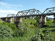
Baltimore truss

Baltimore truss illustrated.
The Baltimore truss is a subclass of the Pratt truss. A Baltimore truss has additional bracing in the lower section of the truss to prevent buckling in the compression members and to control deflection. It is mainly used for rail bridges, showing off a simple and very strong design. Pratt truss uses the intersection of the verticals and the lower horizontal tension members to anchor the supports for the short-span girders under the tracks (among other things). With the Baltimore truss, there are almost twice as many points for this to happen because the short verticals will also be used to anchor the supports. Thus the short-span girders can be made lighter because their span is shorter.
Bollman truss
Bollman truss in Savage, Maryland. Built in 1869, moved to Savage in 1887. It is still in use today as a pedestrian bridge.
39°8′5.42″N 76°49′30.33″W / 39.1348389°N 76.8250917°W / 39.1348389; -76.8250917
The Bollman Truss Railroad Bridge at Savage, Maryland, is the only surviving example of a revolutionary design in the history of American bridge engineering. The type was named for its inventor, Wendel Bollman, a self-educated Baltimore engineer. It was the first successful all-metal bridge design (patented in 1852) to be adopted and consistently used on a railroad. The design employs wrought iron tension members and cast iron compression members. The use of multiple independent tension elements reduces the likelihood of catastrophic failure. The structure was also easy to assemble.
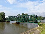
The Wells Creek Bollman Bridge is the only other bridge designed by Wendel Bollman still in existence, but it is a Warren truss configuration.
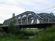
Bowstring arch truss

Bowstring truss illustrated

A bowstring truss bridge, in London, Ontario, Canada
The bowstring arch through truss bridge was patented in 1841[10] by Squire Whipple.[11] While similar in appearance to a tied-arch bridge, a bowstring truss is a truss and thus has diagonal load-bearing members. These diagonals result in a structure that more closely matches a Parker truss or Pratt truss than a true arch.
Brown truss

Brown truss illustrated. With exception of the end posts, all vertical elements are under tension.
This type of truss is particularly suited for timber structures that use iron rods as tension members.
Brunel truss
See Lenticular truss below
Burr arch truss

A covered bridge with a Burr arch truss structure
This combines an arch with a truss to form a structure both strong and rigid.
Cantilevered truss

Forth Bridge
Most trusses have the lower chord under tension and the upper chord under compression. In a cantilever truss the situation is reversed, at least over a portion of the span. The typical cantilever truss bridge is a "balanced cantilever", which enables the construction to proceed outward from a central vertical spar in each direction. Usually these are built in pairs until the outer sections may be anchored to footings. A central gap, if present, can then be filled by lifting a conventional truss into place or by building it in place using a "traveling support". In another method of construction, one outboard half of each balanced truss is built upon temporary falsework. When the outboard halves are completed and anchor the inboard halves may then be constructed and the center section completed as described above.
Fink truss
Fink truss (half span and cross section)
The Fink truss was designed by Albert Fink of Germany in the 1860s. This type of bridge was popular with the Baltimore and Ohio Railroad. The Appomattox High Bridge on the Norfolk and Western Railway included 21 Fink deck truss spans from 1869 until their replacement in 1886.
There are also inverted Fink truss bridges such as the Moody Pedestrian Bridge in Austin, Texas.
Howe truss
Howe truss illustrated – the diagonals are under compression under balanced loading
The relatively rare Howe truss, patented in 1840 by Massachusetts millwright William Howe, includes vertical members and diagonals that slope up towards the center, the opposite of the Pratt truss.[12]
In contrast to the Pratt truss, the diagonal web members are in compression and the vertical web members are in tension. Examples include Jay Bridge in Jay, New York, and Sandy Creek Covered Bridge in Jefferson County, Missouri.
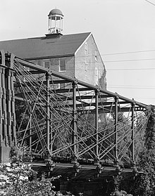
A large timber Howe truss in a commercial building

Jay Bridge showing the truss design


K truss

K-truss

I-895 K-truss
A truss in the form of a K due to the orientation of the vertical member and two oblique members in each panel. An example is the Südbrücke rail bridge over the River Rhine, Mainz, Germany (https://web.archive.org/web/20160304114630/https://ssl.panoramio.com/photo/48902816) and on I-895 (Baltimore Harbor Tunnel Thruway) in Baltimore Maryland.
Kingpost truss

King post truss
One of the simplest truss styles to implement, the king post consists of two angled supports leaning into a common vertical support.
Lattice truss (Town's lattice truss)

Lattice, or Warren quadrangular truss illustrated

Plank lattice truss of a covered bridge
This type of bridge uses a substantial number of lightweight elements, easing the task of construction. Truss elements are usually of wood, iron, or steel.
Lenticular truss

Lenticular, or Pauli truss illustrated

Royal Albert Bridge under construction, 1859

The Ouellette Bridge or Aiken Street Bridge in Lowell, Massachusetts, built in 1883 by the Berlin Iron Bridge Co., is the longest lenticular truss bridge in the country, with 5 spans, as well as the second-oldest lenticular truss bridge in Massachusetts.[13]
A lenticular truss bridge includes a lens-shape truss, with trusses between an upper arch that curves up and then down to end points, and a lower arch that curves down and then up to meet at the same end points. Where the arches extend above and below the roadbed, it is a lenticular pony truss bridge.
One type of lenticular truss consists of arcuate upper compression chords and lower eyebar chain tension links. The Royal Albert Bridge (United Kingdom) uses a single tubular upper chord. As the horizontal tension and compression forces are balanced these horizontal forces are not transferred to the supporting pylons (as is the case with most arch types). This in turn enables the truss to be fabricated on the ground and then to be raised by jacking as supporting masonry pylons are constructed. This truss has been used in the construction of a stadium,[14] with the upper chords of parallel trusses supporting a roof that may be rolled back. The Smithfield Street Bridge in Pittsburgh, Pennsylvania, is another example of this type.
An example of a lenticular pony truss bridge that uses regular spans of iron is the Turn-of-River Bridge designed and manufactured by the Berlin Iron Bridge Co..
Long truss

HAER diagram of a Long Truss
Designed by Stephen H. Long in 1830. The design resembles a Howe truss, but is entirely made of wood instead of a combination of wood and metal.[15] The longest surviving example is the Eldean Covered Bridge north of Troy, Ohio, spanning 224 feet (68 m).[16] One of the earliest examples is the Old Blenheim Bridge, which with a span of 210 feet (64 m) and a total length of 232 feet (71 m) long was the second-longest covered bridge in the United States, until its destruction from flooding in 2011.
The Busching bridge, often erroneously used as an example of a Long truss, is an example of a Howe truss, as the verticals are metal rods.[17] A Long truss has timber verticals.
Parker (camelback) truss
 Parker truss illustrated. |  The Woolsey Bridge is an example of a Parker camelback truss | A Parker truss bridge is a Pratt truss design with a polygonal upper chord. A "camelback" is a subset of the Parker type, where the upper chord consists of exactly five segments. An example of a Parker truss is the Traffic Bridge in Saskatoon, Canada. An example of a camelback truss is the Woolsey Bridge near Woolsey, Arkansas. |
Pegram truss

Pegram truss
The Pegram truss is a hybrid between the Warren and Parker trusses where the upper chords are all of equal length and the lower chords are longer than the corresponding upper chord. Because of the difference in upper and lower chord length, each panel is not square. The members which would be vertical in a Parker truss vary from near vertical in the center of the span to diagonal near each end (like a Warren truss). George H. Pegram, while the chief engineer of Edge Moor Iron Company in Wilmington, Delaware, patented this truss design in 1885.[18]
The Pegram truss consists of a Parker type design with the vertical posts leaning towards the center at an angle between 60 and 75°. The variable post angle and constant chord length allowed steel in existing bridges to be recycled into a new span using the Pegram truss design. This design also facilitated reassembly and permitted a bridge to be adjusted to fit different span lengths. There are twelve known remaining Pegram span bridges in the United States with seven in Idaho, two in Kansas, and one each in California, Washington, and Utah.[citation needed]
Pennsylvania (Petit) truss

Pennsylvania, or Petit truss illustrated.

The Fair Oaks Bridge is an example of Pennsylvania Petit truss bridge.
The Pennsylvania (Petit) truss is a variation on the Pratt truss.[19] The Pratt truss includes braced diagonal members in all panels; the Pennsylvania truss adds to this design half-length struts or ties in the top, bottom, or both parts of the panels. It is named after the Pennsylvania Railroad, which pioneered this design. It was once used for hundreds of bridges in the United States, but fell out of favor in the 1930s, and very few bridges of this design remain.[20] Examples of this truss type include the Lower Trenton Bridge in Trenton, New Jersey, the Schell Bridge in Northfield, Massachusetts, the Inclined Plane Bridge in Johnstown, Pennsylvania, the Easton–Phillipsburg Toll Bridge in Easton, Pennsylvania and the Healdsburg Memorial Bridge in Healdsburg, California.
Post truss

A Post truss
A Post truss is a hybrid between a Warren truss and a double-intersection Pratt truss. Invented in 1863 by Simeon S. Post, it is occasionally referred to as a Post patent truss although he never received a patent for it.[21] The Ponakin Bridge and the Bell Ford Bridge are two examples of this truss.
Pratt truss
Pratt truss
Gatton Railway Bridge showing the Pratt truss design
A Pratt truss includes vertical members and diagonals that slope down towards the center, the opposite of the Howe truss.[12] The interior diagonals are under tension under balanced loading and vertical elements under compression. If pure tension elements are used in the diagonals (such as eyebars) then crossing elements may be needed near the center to accept concentrated live loads as they traverse the span. It can be subdivided, creating Y- and K-shaped patterns. The Pratt truss was invented in 1844 by Thomas and Caleb Pratt.[22] This truss is practical for use with spans up to 250 feet (76 m) and was a common configuration for railroad bridges as truss bridges moved from wood to metal. They are statically determinate bridges, which lend themselves well to long spans. They were common in the United States between 1844 and the early 20th century.[22]
Examples of Pratt through truss bridges are the Governor's Bridge in Maryland,[22]Dearborn River High Bridge near Augusta, Montana, built in 1897, and the Fair Oaks Bridge in Fair Oaks, California, built 1907–09.
The Scenic Bridge near Tarkio, Montana is an example of a Pratt deck truss bridge, where the roadway is on top of the truss.
Queenpost truss

Queen post truss
The queenpost truss, sometimes "queen post" or "queenspost", is similar to a king post truss in that the outer supports are angled towards the center of the structure. The primary difference is the horizontal extension at the center which relies on beam action to provide mechanical stability. This truss style is only suitable for relatively short spans.[23]
Smith truss

Smith post truss
Patented by Robert W Smith on July 16, 1867[24], the smith truss has mostly diagonal criss crossed supports. Smith's company used many variations of this pattern in the wooden covered bridges it built.
Thatcher truss

Thatcher Truss illustrated
The Thatcher truss combines some of the characteristics of a Pratt truss with diagonals under tension and a Howe truss with diagonals under compression. It is quite rare.
Truss arch

Truss arch bridge illustration
A truss arch may contain all horizontal forces within the arch itself, or alternatively may be either a thrust arch consisting of a truss, or of two arcuate sections pinned at the apex. The latter form is common when the bridge is constructed as cantilever segments from each side as in the Navajo Bridge.
Vierendeel truss
A Vierendeel bridge
The Vierendeel truss, unlike common pin-jointed trusses, imposes significant bending forces upon its members — but this in turn allows the elimination of many diagonal elements. It is a structure where the members are not triangulated but form rectangular openings, and is a frame with fixed joints that are capable of transferring and resisting bending moments. While rare as a bridge type due to higher costs compared to a triangulated truss, it is commonly employed in modern building construction as it allows the resolution of gross shear forces against the frame elements while retaining rectangular openings between columns. This is advantageous both in allowing flexibility in the use of the building space and freedom in selection of the building's outer curtain wall, which affects both interior and exterior styling aspects.
Waddell truss

Waddell "A" truss (1898 bridge)
Patented 1894 (U.S. Patent 529,220) its simplicity eases erection at the site. It was intended to be used as a railroad bridge.
One example was the Waddell "A" Truss Bridge (Parkville, Missouri)
Warren truss
Warren truss illustrated – some of the diagonals are under compression and some under tension
The Warren truss was patented in 1848 by James Warren and Willoughby Theobald Monzani, and consists of longitudinal members joined only by angled cross-members, forming alternately inverted equilateral triangle-shaped spaces along its length, ensuring that no individual strut, beam, or tie is subject to bending or torsional straining forces, but only to tension or compression. Loads on the diagonals alternate between compression and tension (approaching the center), with no vertical elements, while elements near the center must support both tension and compression in response to live loads. This configuration combines strength with economy of materials and can therefore be relatively light. The girders being of equal length, it is ideal for use in prefabricated modular bridges. It is an improvement over the Neville truss which uses a spacing configuration of isosceles triangles.
Whipple truss

Whipple truss illustrated

Whipple truss illustrated

Bridge L-158
A Whipple truss, named after its inventor Squire Whipple, is usually considered a subclass of the Pratt truss because the diagonal members are designed to work in tension. The main characteristic of a Whipple truss is that the tension members are elongated, usually thin, and at a shallow angle, and cross two or more bays (rectangular sections defined by the vertical members).
Truss bridge video
Driving across a truss bridge:
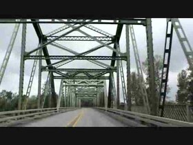 Play media
References
Historic American Engineering Record (1976). "Trusses: A Study by the Historic American Engineering Record" (PDF). National Park Service. Retrieved 2015-05-29..mw-parser-output cite.citation{font-style:inherit}.mw-parser-output q{quotes:"""""""'""'"}.mw-parser-output code.cs1-code{color:inherit;background:inherit;border:inherit;padding:inherit}.mw-parser-output .cs1-lock-free a{background:url("//upload.wikimedia.org/wikipedia/commons/thumb/6/65/Lock-green.svg/9px-Lock-green.svg.png")no-repeat;background-position:right .1em center}.mw-parser-output .cs1-lock-limited a,.mw-parser-output .cs1-lock-registration a{background:url("//upload.wikimedia.org/wikipedia/commons/thumb/d/d6/Lock-gray-alt-2.svg/9px-Lock-gray-alt-2.svg.png")no-repeat;background-position:right .1em center}.mw-parser-output .cs1-lock-subscription a{background:url("//upload.wikimedia.org/wikipedia/commons/thumb/a/aa/Lock-red-alt-2.svg/9px-Lock-red-alt-2.svg.png")no-repeat;background-position:right .1em center}.mw-parser-output .cs1-subscription,.mw-parser-output .cs1-registration{color:#555}.mw-parser-output .cs1-subscription span,.mw-parser-output .cs1-registration span{border-bottom:1px dotted;cursor:help}.mw-parser-output .cs1-hidden-error{display:none;font-size:100%}.mw-parser-output .cs1-visible-error{font-size:100%}.mw-parser-output .cs1-subscription,.mw-parser-output .cs1-registration,.mw-parser-output .cs1-format{font-size:95%}.mw-parser-output .cs1-kern-left,.mw-parser-output .cs1-kern-wl-left{padding-left:0.2em}.mw-parser-output .cs1-kern-right,.mw-parser-output .cs1-kern-wl-right{padding-right:0.2em}
Footnotes
^ Science and Industry, Members of a Truss Bridge by Benj. F. La Rue, Home Study Magazine, Published by the Colliery Engineer Company, Vol 3, No. 2, March 1898, pages 67-68.
^ "Temporary Skagit River bridge may be open in weeks". King 5 television. May 26, 2013. Archived from the original on June 7, 2013. Retrieved March 27, 2013.
^ "Timber Truss Bridges" (PDF). McMillan Britton & Kell Pty Limited. Roads and Traffic Authority. December 1998. Retrieved 23 November 2010.
^ "Tharwa Bridge Conservation Management Plan" (PDF). Philip Leeson Architects. Roads ACT. 5 March 2009. pp. 42, 45. Retrieved 23 November 2010.
^ "1307.8 – Australian Capital Territory in Focus, 2007". Australian Bureau of Statistics. 27 November 2007. Retrieved 23 November 2010.
^ "Tharwa Bridge". Engineers Australia. Canberra's Engineering Heritage. Retrieved 23 November 2010.
^ "Minutes of State Heritage Register Committee meeting" (PDF). State Heritage Register Committee. Heritage Council of New South Wales. 5 November 2008. p. 5. Archived from the original (PDF) on 17 March 2011. Retrieved 23 November 2010.
^ "Hampden Bridge, Wagga Wagga, NSW". Timber Building in Australia. Archived from the original on 2013-05-12. Retrieved 2008-06-05.
^ Google-maps "-34.180255,150.610654" clearly shows bridge with traffic
^ U.S. Patent 2,064
^ Gardner, Denis P. (2008). Wood, Concrete, Stone, Steel: Minnesota's Historic Bridges. Minneapolis: University of Minnesota Press. p. 51. ISBN 978-0-8166-4666-1.
^ ab Matsuo Bridge Company, Bridge Types – Truss Archived 2006-09-05 at the Wayback Machine., accessed September 2007
^ "Aiken Street Bridge: Ouellette Bridge". HistoricBridges.org. 2018. Retrieved 9 July 2018.
^ "Arizona Cardinals Stadium". Archived from the original on 2007-11-03. Retrieved 2008-04-28.
^ CoveredBridgeSite, Long truss
^ Eldean Covered Bridge – Troy, Ohio – Covered Bridges on. Waymarking.com. Retrieved on 2013-07-23.
^ "Busching Bridge". CLR Inc. Construction and Transportation. Archived from the original on August 20, 2011. Retrieved June 25, 2012.
^ US 314262, Pegram, George H., "Truss for Roofs and Bridges", published 10-24-1881, issued 03-24-1885
^ Bridge Basics – A Spotter's Guide
^ National Register of Historic Places Registration Form for Healdsburg Memorial Bridge, California State Park System, accessed 2011-12-26.
^ Jackson, Donald C. (1995). Great American Bridges and Dams. New York: John Wiley & Sons. p. 92. ISBN 978-0-471-14385-7.
^ abc
Maryland Historical Trust Property Number PG-74B-1 & AA-85I (PDF), Maryland Inventory of Historic Bridges, retrieved 5 January 2013
^ Covered Bridge's Truss Types Archived 2006-09-04 at the Wayback Machine.
^ "R.W. Smith Truss Patent 66,900". United States Patent Office. United States of America. July 16, 1867. Retrieved 10 November 2018.
External links
| Wikimedia Commons has media related to Through truss bridges and Truss drawings. |
Bridge Basics – A Spotter's Guide to Bridge Design – from Pghbridges.com – Illustrates many of the various types of truss arrangements used in bridges.
Historic Bridges of Michigan and Elsewhere – Many photos of truss bridges are available on this informative and mainly truss-focused bridge website.
Historic Bridges of Iowa – An illustrated list of different architectural bridge types found in Iowa, USA. Many of these are truss bridges.
Historic Bridges of the U.S. – An enormous database of historic bridges. Over 17,400 truss bridges are listed here.
Iron and Early Steel Bridges of Ohio A comprehensive inventory of all remaining truss bridges in Ohio. Includes maps, photos, and invites visitor assistance in identifying extant or demolished bridges.- Matsuo Bridge Company: Bridge Types – Truss
Management Plan for Historic Bridges in Virginia: The 2017 Update -- Virginia Department of Transportation's plan for managing its historic bridges, including metal truss bridges. The update includes sections on study findings such as "General Issues Regarding Metal and Metal Truss Bridges (Including Potential Life Span)," "Coatings Issues for Metal Truss Bridges: Painting, Metallizing, and Galvanizing," and "Truss Bridge Capacity and Overloading Potential."
structurae.de The Structurae database on bridges.
| Structural types |
|  |
|---|---|---|
| Lists of bridges by type |
| |
| Lists of bridges by size |
| |
| Additional lists |
| |
| ||
Authority control |
|
|---|


