Line-of-sight propagation

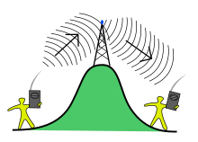
Line of sight propagation to an antenna
Line-of-sight propagation is a characteristic of electromagnetic radiation or acoustic wave propagation which means waves travel in a direct path from the source to the receiver. Electromagnetic transmission includes light emissions traveling in a straight line. The rays or waves may be diffracted, refracted, reflected, or absorbed by the atmosphere and obstructions with material and generally cannot travel over the horizon or behind obstacles.
In contrast to line-of-sight propagation, at low frequency (below approximately 3 MHz) due to diffraction, radio waves can travel as ground waves, which follow the contour of the Earth. This enables AM radio stations to transmit beyond the horizon. Additionally, frequencies in the shortwave bands between approximately 1 and 30 MHz, can be reflected back to Earth by the ionosphere, called skywave or "skip" propagation, thus giving radio transmissions in this range a potentially global reach.
However, at frequencies above 30 MHz (VHF and higher) and in lower levels of the atmosphere, neither of these effects are significant. Thus, any obstruction between the transmitting antenna (transmitter) and the receiving antenna (receiver) will block the signal, just like the light that the eye may sense. Therefore, since the ability to visually see a transmitting antenna (disregarding the limitations of the eye's resolution) roughly corresponds to the ability to receive a radio signal from it, the propagation characteristic at these frequencies is called "line-of-sight". The farthest possible point of propagation is referred to as the "radio horizon".
In practice, the propagation characteristics of these radio waves vary substantially depending on the exact frequency and the strength of the transmitted signal (a function of both the transmitter and the antenna characteristics). Broadcast FM radio, at comparatively low frequencies of around 100 MHz, are less affected by the presence of buildings and forests.
Contents
1 Impairments to line-of-sight propagation
2 Mobile telephones
3 Radio horizon
3.1 Earth bulge and atmosphere effect
3.2 Geometric distance to horizon
3.3 The actual service range
3.4 Example
4 See also
5 References
6 External links
Impairments to line-of-sight propagation

Objects within the Fresnel zone can disturb line of sight propagation even if they don't block the geometric line between antennas.
Low-powered microwave transmitters can be foiled by tree branches, or even heavy rain or snow. The presence of objects not in the direct line-of-sight can cause diffraction effects that disrupt radio transmissions. For the best propagation, a volume known as the first Fresnel zone should be free of obstructions.
Reflected radiation from the surface of the surrounding ground or salt water can also either cancel out or enhance the direct signal. This effect can be reduced by raising either or both antennas further from the ground: The reduction in loss achieved is known as height gain.
See also Non-line-of-sight propagation for more on impairments in propagation.
It is important to take into account the curvature of the Earth for calculation of line-of-sight paths from maps, when a direct visual fix cannot be made. Designs for microwave formerly used 4⁄3 earth radius to compute clearances along the path.
Mobile telephones
Although the frequencies used by mobile phones (cell phones) are in the line-of-sight range, they still function in cities. This is made possible by a combination of the following effects:
- 1⁄r 4 propagation over the rooftop landscape[clarification needed]
- diffraction into the "street canyon" below
multipath reflection along the street- diffraction through windows, and attenuated passage through walls, into the building
- reflection, diffraction, and attenuated passage through internal walls, floors and ceilings within the building
The combination of all these effects makes the mobile phone propagation environment highly complex, with multipath effects and extensive Rayleigh fading. For mobile phone services, these problems are tackled using:
- rooftop or hilltop positioning of base stations
- many base stations (usually called "cell sites"). A phone can typically see at least three, and usually as many as six at any given time.
- "sectorized" antennas at the base stations. Instead of one antenna with omnidirectional coverage, the station may use as few as 3 (rural areas with few customers) or as many as 32 separate antennas, each covering a portion of the circular coverage. This allows the base station to use a directional antenna that is pointing at the user, which improves the signal to noise ratio. If the user moves (perhaps by walking or driving) from one antenna sector to another, the base station automatically selects the proper antenna.
- rapid handoff between base stations (roaming)
- the radio link used by the phones is a digital link with extensive error correction and detection in the digital protocol
- sufficient operation of mobile phone in tunnels when supported by split cable antennas
- local repeaters inside complex vehicles or buildings
A Faraday cage is composed of a conductor that completely surrounds an area on all sides, top, and bottom. Electromagnetic radiation is blocked where the wavelength is longer than any gaps. For example, mobile telephone signals are blocked in windowless metal enclosures that approximate a Faraday cage, such as elevator cabins, and parts of trains, cars, and ships. The same problem can affect signals in buildings with extensive steel reinforcement.

Two stations not in line-of-sight may be able to communicate through an intermediate radio repeater station.
Radio horizon
The radio horizon is the locus of points at which direct rays from an antenna are tangential to the surface of the Earth. If the Earth were a perfect sphere without an atmosphere, the radio horizon would be a circle.
The radio horizon of the transmitting and receiving antennas can be added together to increase the effective communication range.
Radio wave propagation is affected by atmospheric conditions, ionospheric absorption, and the presence of obstructions, for example mountains or trees.
Simple formulas that include the effect of the atmosphere give the range as:
- horizonmiles≈1.23⋅heightfeet.{displaystyle mathrm {horizon} _{mathrm {miles} }approx 1.23cdot {sqrt {mathrm {height} _{mathrm {feet} }}}.}
- horizonkm≈3.57⋅heightmetres{displaystyle mathrm {horizon} _{mathrm {km} }approx 3.57cdot {sqrt {mathrm {height} _{mathrm {metres} }}}}
The simple formulas give a best-case approximation of the maximum propagation distance, but are not sufficient to estimate the quality of service at any location.
Earth bulge and atmosphere effect
Earth bulge is a term used in telecommunications. It refers to the circular segment of earth profile that blocks off long distance communications. Since the geometric line of sight passes at varying heights over the Earth, the propagating radio wave encounters slightly different propagation conditions over the path. The usual effect of the declining pressure of the atmosphere with height is to bend radio waves down towards the surface of the Earth, effectively increasing the Earth's radius, and the distance to the radio horizon, by a factor around 4⁄3.[1] This k-factor can change from its average value depending on weather.
Geometric distance to horizon

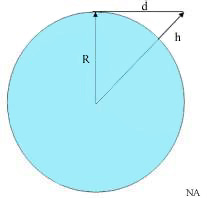
R is the radius of the Earth, h is the height of the transmitter (exaggerated), d is the line of sight distance
Assuming a perfect sphere with no terrain irregularity, the distance to the horizon from a high altitude transmitter (i.e., line of sight) can readily be calculated.
Let R be the radius of the Earth and h be the altitude of a telecommunication station. The line of sight distance d of this station is given by the Pythagorean theorem;
- d2=(R+h)2−R2=2⋅R⋅h+h2{displaystyle d^{2}=(R+h)^{2}-R^{2}=2cdot Rcdot h+h^{2}}
Since the altitude of the station is much less than the radius of the Earth,
- d≈2⋅R⋅h{displaystyle dapprox {sqrt {2cdot Rcdot h}}}
If the height is given in metres, and distance in kilometres,[2]
- d≈3.57⋅h{displaystyle dapprox 3.57cdot {sqrt {h}}}
If the height is given in feet, and the distance in miles,
- d≈1.23⋅h{displaystyle dapprox 1.23cdot {sqrt {h}}}
The actual service range
The above analysis does not consider the effect of atmosphere on the propagation path of RF signals. In fact, RF signals don’t propagate in straight lines: Because of the refractive effects of atmospheric layers, the propagation paths are somewhat curved. Thus, the maximum service range of the station is not equal to the line of sight (geometric) distance. Usually, a factor k is used in the equation above, modified to be
- d≈2⋅k⋅R⋅h{displaystyle dapprox {sqrt {2cdot kcdot Rcdot h}}}
k > 1 means geometrically reduced bulge and a longer service range. On the other hand, k < 1 means a shorter service range.
Under normal weather conditions, k is usually chosen[3] to be 4⁄3. That means that the maximum service range increases by 15%.
- d≈4.12⋅h{displaystyle dapprox 4.12cdot {sqrt {h}}}
for h in metres and d in kilometres; or
- d≈1.41⋅h{displaystyle dapprox 1.41cdot {sqrt {h}}}
for h in feet and d in miles.
But in stormy weather, k may decrease to cause fading in transmission. (In extreme cases k can be less than 1.) That is equivalent to a hypothetical decrease in Earth radius and an increase of Earth bulge.[4]
Example
In normal weather conditions, the service range of a station at an altitude of 1500 m with respect to receivers at sea level can be found as,
- d≈4.12⋅1500=160 km.{displaystyle dapprox 4.12cdot {sqrt {1500}}=160{mbox{ km.}}}
See also
- Anomalous propagation
- Field strength in free space
- Knife-edge effect
- Multilateration
- Non-line-of-sight propagation
- Over-the-horizon radar
- Radial (radio)
Rician fading, stochastic model of line-of-sight propagation- Slant range
References
^ Christopher Haslett. (2008). Essentials of radio wave propagation, pp 119–120. Cambridge University Press. .mw-parser-output cite.citation{font-style:inherit}.mw-parser-output q{quotes:"""""""'""'"}.mw-parser-output code.cs1-code{color:inherit;background:inherit;border:inherit;padding:inherit}.mw-parser-output .cs1-lock-free a{background:url("//upload.wikimedia.org/wikipedia/commons/thumb/6/65/Lock-green.svg/9px-Lock-green.svg.png")no-repeat;background-position:right .1em center}.mw-parser-output .cs1-lock-limited a,.mw-parser-output .cs1-lock-registration a{background:url("//upload.wikimedia.org/wikipedia/commons/thumb/d/d6/Lock-gray-alt-2.svg/9px-Lock-gray-alt-2.svg.png")no-repeat;background-position:right .1em center}.mw-parser-output .cs1-lock-subscription a{background:url("//upload.wikimedia.org/wikipedia/commons/thumb/a/aa/Lock-red-alt-2.svg/9px-Lock-red-alt-2.svg.png")no-repeat;background-position:right .1em center}.mw-parser-output .cs1-subscription,.mw-parser-output .cs1-registration{color:#555}.mw-parser-output .cs1-subscription span,.mw-parser-output .cs1-registration span{border-bottom:1px dotted;cursor:help}.mw-parser-output .cs1-hidden-error{display:none;font-size:100%}.mw-parser-output .cs1-visible-error{font-size:100%}.mw-parser-output .cs1-subscription,.mw-parser-output .cs1-registration,.mw-parser-output .cs1-format{font-size:95%}.mw-parser-output .cs1-kern-left,.mw-parser-output .cs1-kern-wl-left{padding-left:0.2em}.mw-parser-output .cs1-kern-right,.mw-parser-output .cs1-kern-wl-right{padding-right:0.2em}
ISBN 052187565X.
^ Mean radius of the Earth is ≈ 6.37×10⁶ metres = 6370 km. See Earth radius
^ Busi, R. (1967). High Altitude VHF and UHF Broadcasting Stations. Technical Monograph 3108-1967. Brussels: European Broadcasting Union.
^ This analysis is for high altitude to sea level reception. In microwave radio link chains, both stations are at high altitudes.
External links
- http://web.telia.com/~u85920178/data/pathlos.htm#bulges
- Article on the importance of Line Of Sight for UHF reception
- Attenuation Levels Through Roofs
- Approximating 2-Ray Model by using Binomial series by Matthew Bazajian
![]() This article incorporates public domain material from the General Services Administration document "Federal Standard 1037C" (in support of MIL-STD-188).
This article incorporates public domain material from the General Services Administration document "Federal Standard 1037C" (in support of MIL-STD-188).


